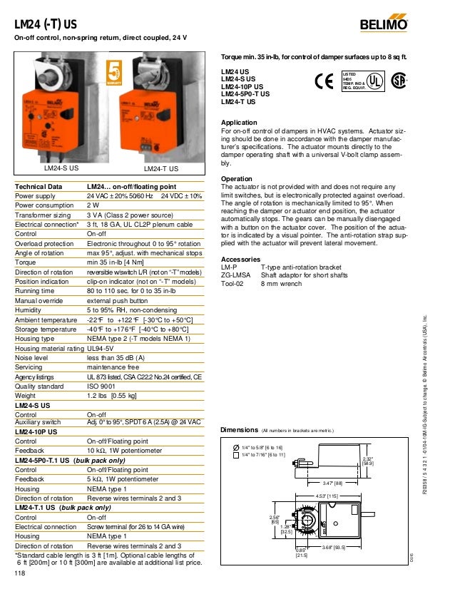
Actuator type non fail safe angle of rotation 90 application water control type floating3 point degree of protection ip54 nema 2 ul enclosure type 2. Nsv24 us battery back up module wiring diagrams vdc4 20 ma.

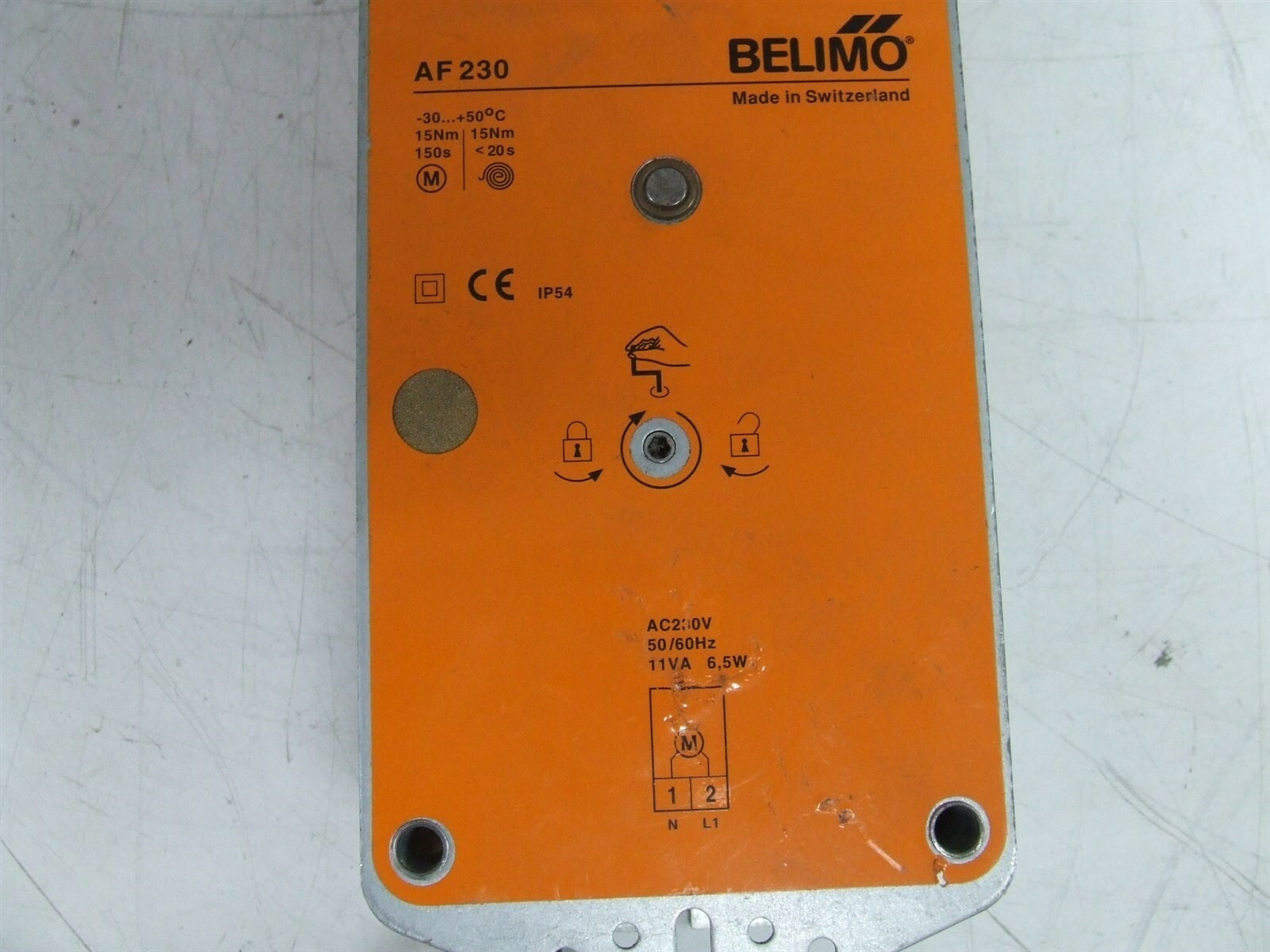
Details About Belimo Af 230 Spring Return Damper Actuator 15nm 230v Ac
Belimo lrb24 3 wiring diagram. Lrb24 3 technical data sheet 800 543 9038 usa 866 805 7089 canada 203 791 8396 latin america caribbean. Lrb24 3 s technical data sheet onoff floating point non spring return 24 v 800 543 9038 usa 866 805 7089 canada 203 791 8396 latin america caribbean. Pre set and cus technical data lmx24 mft95 tom configurations from belimo or on site configurations using power supply 24 vac 20 5060 hz the belimo pc tool software. Variety of belimo lrb24 3 wiring diagram it is possible to download totally free. Actuators shall be as manufactured by belimo. Actuators may be connected in parallel.
Wiring diagrams installation notes provide overload protection and disconnect as required. Understanding wiring diagrams analog outputs wiring diagrams for belimo products applications specifications 24 vac transformer line volts 1 com mon 2 hot af24 us nf24 us lf24 us 24 vac transformer 2 to 10 vdc feedback signal line volts blk 1 common red 2 hot wht 3 y 1 input 2 to 10 v 4 y 2 grn 5 output 2 to 10v control. Rated impulse voltage 800v type action 1b control pollution degree 3. Please download these belimo lrb24 3 wiring diagram by using the download button or right visit selected image then use save image menu. Wiring diagrams help technicians to see the way the controls are wired to the system. Power consumption and input impedance must be observed.
Assortment of belimo lrb24 3 wiring diagram. Lrb24 mft technical data sheet modulating non spring return 24 v multi function technology 800 543 9038 usa 866 805 7089 canada 203 791 8396 latin america caribbean. It reveals the components of the circuit as simplified forms and the power and signal connections between the gadgets. Page 21 the parameters can be changed by two means. A wiring diagram is a simplified conventional photographic depiction of an electric circuit. A wiring diagram is a simplified conventional pictorial depiction of an electrical circuit.
It reveals the components of the circuit as simplified forms and the power and also signal links in between the devices. Auxiliary switch 1 x spdt 3 a resistive 05 a inductive at ac 250 v adjustable 0100 rated impulse voltage 800v type action 1 control pollution degree 3. Actuators may also be powered by 24 vdc. Assortment of belimo lrb24 3 wiring diagram. Only connect common to negative leg of control circuits.


