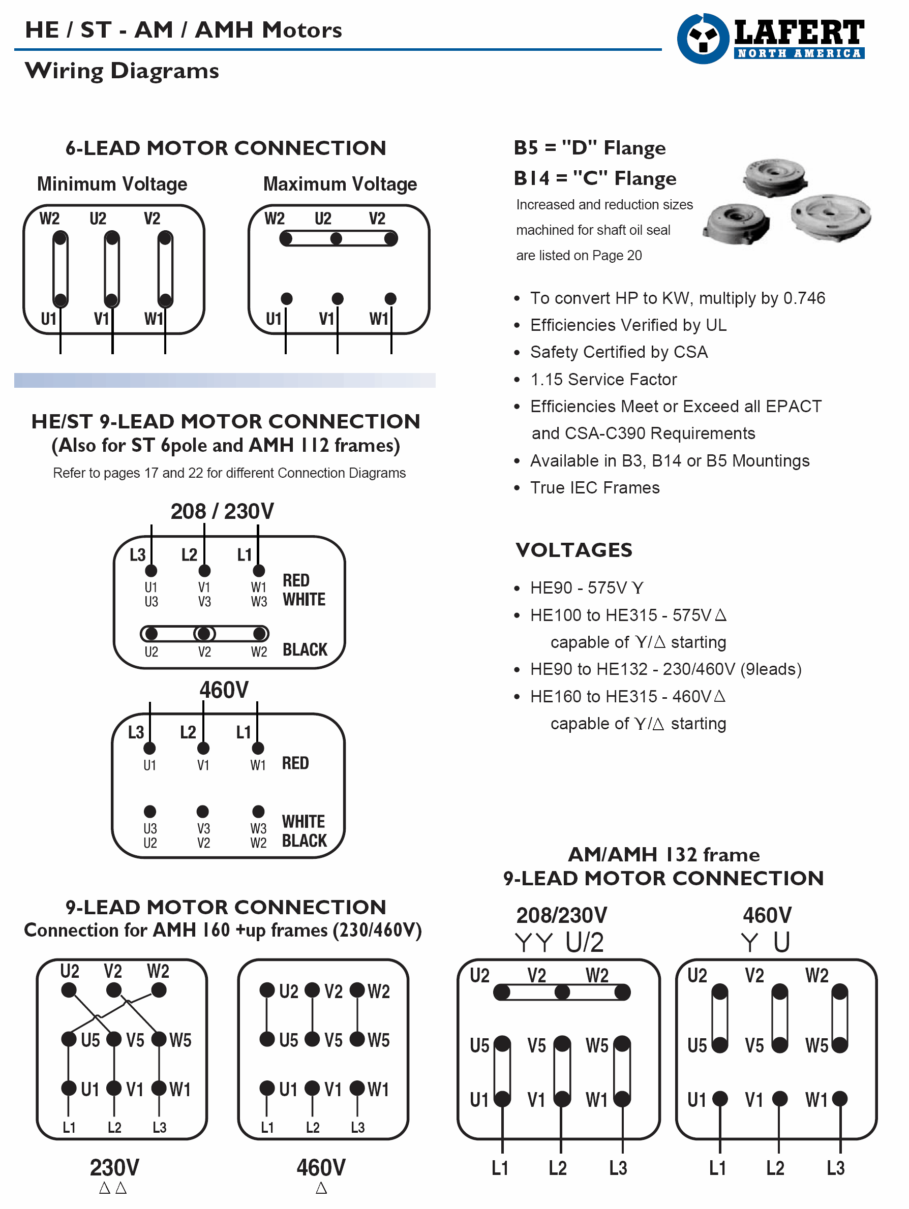
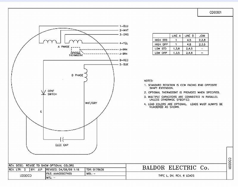
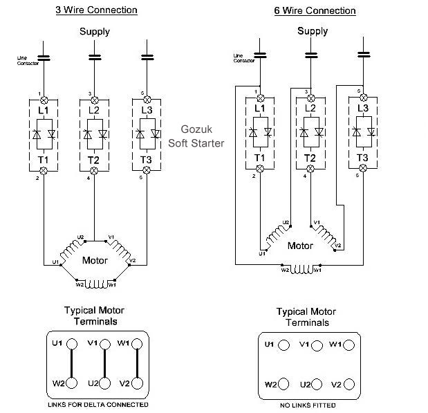
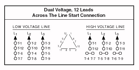
A wiring diagram is a streamlined traditional photographic depiction of an electrical circuit. Baldor electric motor wiring diagram beautiful baldor 12 lead motor 12 lead motor wiring diagram.

Tf 4363 Baldor 115 Volt Motor Wiring Diagram Schematic Wiring
Baldor 12 lead motor wiring diagram. Wiring diagram not merely provides in depth illustrations of what you can perform but additionally the procedures you should follow while carrying out so. You need to refer to the individual plate for your particular electric motor when wiring it as wiring procedures may be different particularly between ac and dc motors. Each type of baldor electric motor has labeled wiring diagrams on a plate fixed on the motor. Typical connection diagrams three phase motors y start delta. 3 phase 6 lead motor wiring diagram elegant awesome 12 lead 3 phase. 12 lead motor wiring diagram baldor photographs and photos assortment this posted listed here ended up being correctly chosen plus.
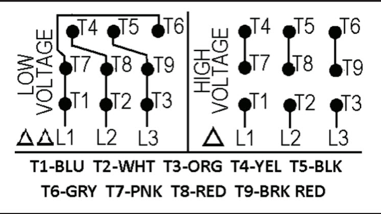
We all attain this specific marvelous photographs online and choose the most effective to get you. On a 12 wire motor wired for high voltage ie 480v 10t 11t and 12t must be connected together but not connected to anything else. The other 9 wires would be connected as in a 9 wire motor note in a 9 wire motor the equivalent of t10 t11 and t12 are internally connected together. Collection of baldor single phase motor wiring diagram. Typical connection diagrams three phase motors y start delta. This particular 12 lead motor wiring diagram baldor wonderful illustrations or photos picks in relation to wiring schematic is available so that you can save.
3 phase motor wiring diagram 12 leads sample how to check polarity of each winding in 3 phase motor. L1 to t1 l2 to t2 l3 to t3 t4 to t7 t5 to t8 and t6. It shows the elements of the circuit as streamlined shapes as well as the power and signal links in between the tools.


