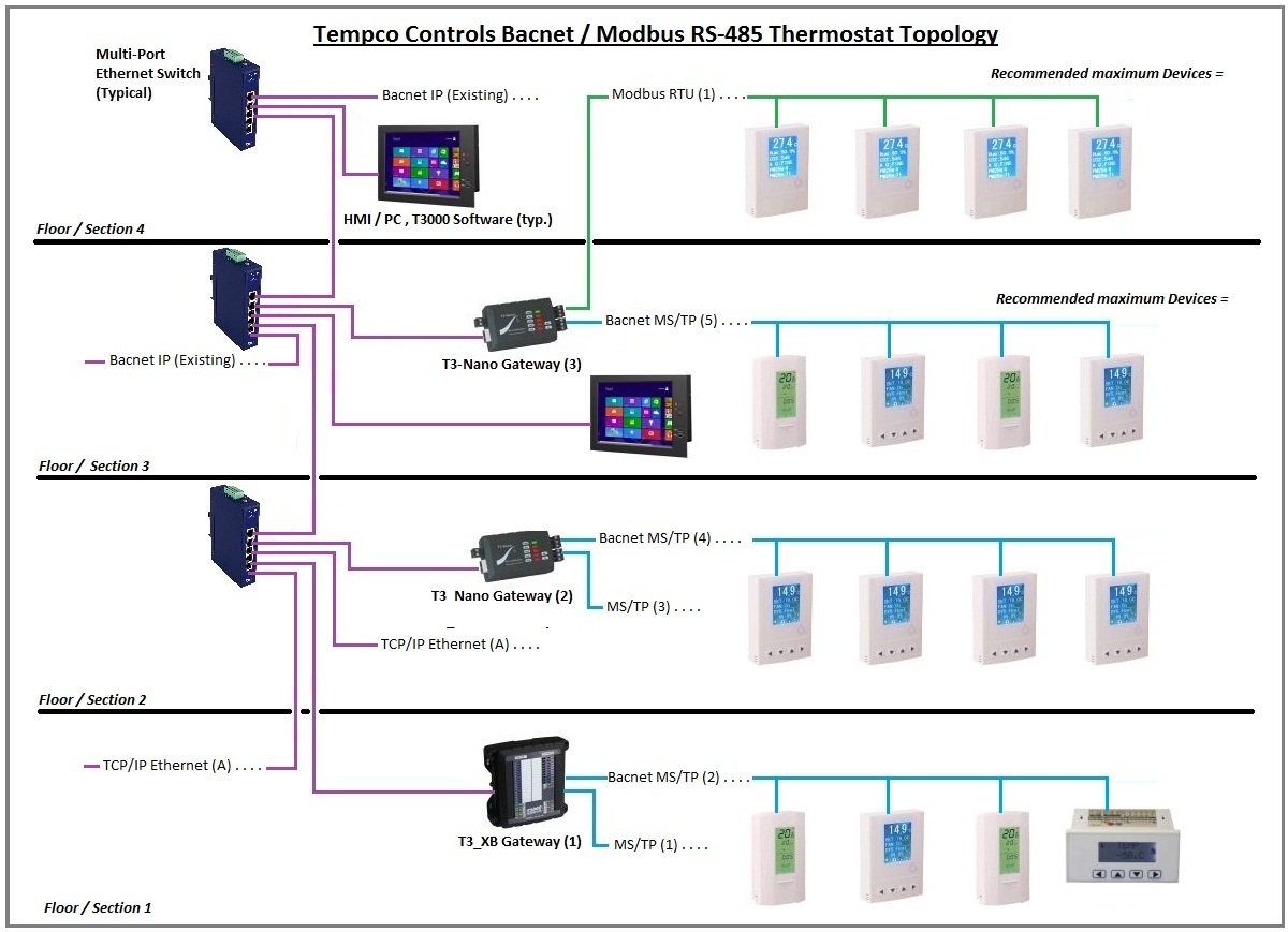
0 8n1 1 8n2 2 8e1 3 8o1. This type of network is low bandwidth but reliable and good for long distance multi drop runs.

Controller Bacnet Ip 750 831 Wago
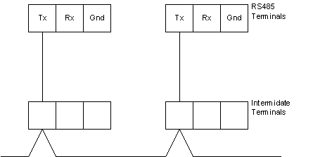
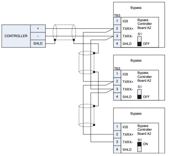
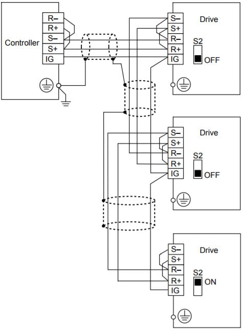
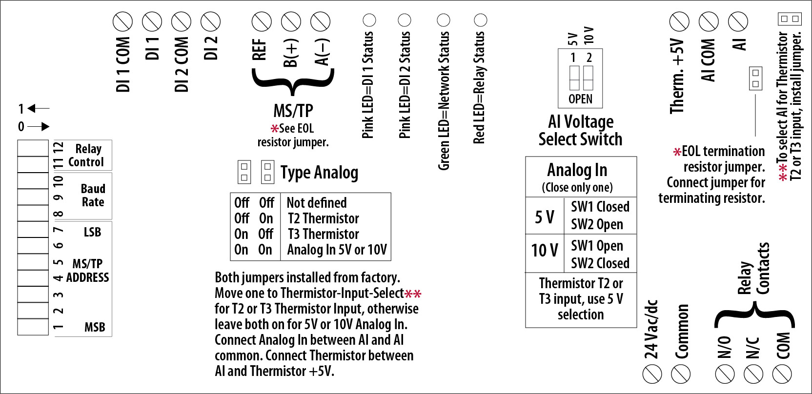
Bacnet wiring diagram. A temporary value of 0 places the protocol channel in reset. Turn on the main electrical power to the appliance. This guide provides the following discussions. As shown in the bacnet sample wiring diagram the position of jumpers on each 340bn transmitter and wiring between each 340bn transmitter and the bacnet network are different depend ing on where the transmitter is installed ie. Perform the wiring connections referencing figs 2 6b and 2 6c. Confi gure the control board and unit controls per this manual and resume operation.
4 20ma user scaled. Bacnet wiring guidelines product overview wire routing bacnet mstp networks must be wired in a daisy chain configuration. F 27360 11 micronet bacnet wiring networking and best practices guide ix preface purpose of this manual this tac ia series micronet bacnet wiring networking and best practices guide is a reference for creating a network of tac ia series micronet bacnet controllers. Thermistor 10k ohm type iii temperature sensors 3. 1 5303 efb baud rate 38400 this parameter sets the bacnet mstp baud rate. 5302 efb station id 128 this parameter sets the drives bacnet mstp mac id.
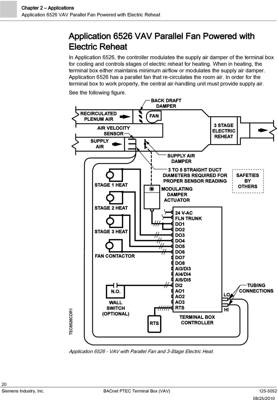
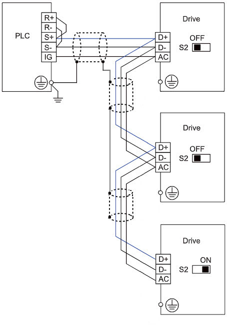
5304 efb parity 0 this parameter sets the bacnet mstp character format as follows. Bgc wiring diagram oe338 26b bgc bacnet general controller binary inputs bin1 through bin8 applying 24vac activates each input analog inputs ai1through ai8 configured for the following. A daisy chain means that there is only one main cable and every network device is connected directly along its path. Wiring bacnet general controller technical guide 7 bgc wiring figure 2. Connection board wiring harnesses. Secure the wiring with the provided cable clips and route it through the bottom of the control panel.
