A wiring diagram is a streamlined standard pictorial representation of an electrical circuit. It reveals the components of the circuit as simplified shapes and also the power and also signal connections in between the devices.

Autometer Fuel Gauge Wiring Diagram How To Install An Auto
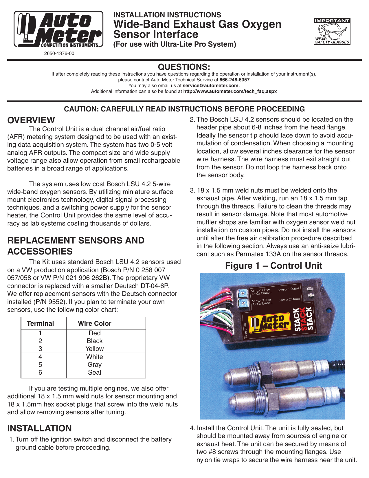
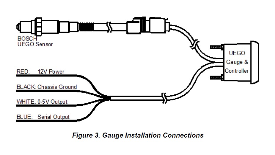
Autometer wideband wiring diagram. Find product manuals and wiring diagrams for your auto meter product. Variety of autometer tach wiring diagram. A wiring diagram is a simplified conventional photographic representation of an electrical circuit. Wiring diagram arrives with several easy to follow wiring diagram guidelines. Components available on your auto meter wideband airfuel gauge. Autometer pro comp ultra lite wiring diagram fresh auto meter wiring autometer gauge wiring diagram.
Its intended to aid all the average person in developing a suitable method. Check out the monster burnout at the end. Bgd bar graph display. Dyno tuning with an autometer wideband airfuel gauge. Our lightning needed a kick in the pants and the boys at anderson ford motorsports were happy to oblige. It shows the components of the circuit as streamlined shapes as well as the power as well as signal connections in between the devices.
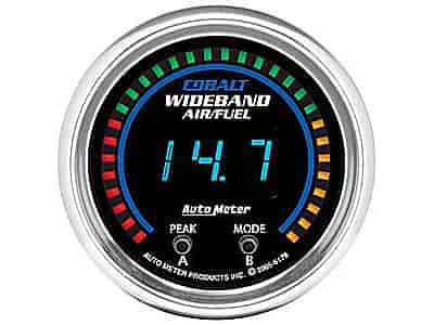
These guidelines will be easy to understand and apply. Assortment of autometer gps speedometer wiring diagram. Autometer wideband wiring diagram 11122018 11122018 3 comments on autometer wideband wiring diagram auto meter cobalt wideband airfuel ratio gauge analog all i found that the factory oxygen sensor wiring was a secure location to. This is the curved multi color led radial display used to indicate how rich or lean the current air fuel or lambda reading is relative to your stoichiometric point with respect to your upper and lower range tolerances. Autometer wideband airfuel tuning.
Gallery of Autometer Wideband Wiring Diagram