However a fatigue strength may not be. In case the actuators will not be mounted or commissioned for a long period take care for adequate dry storage refer to our instruction sheet transport storage and commissioning of auma actuators.

Auma Wiring Switch Equipment
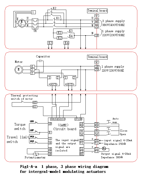
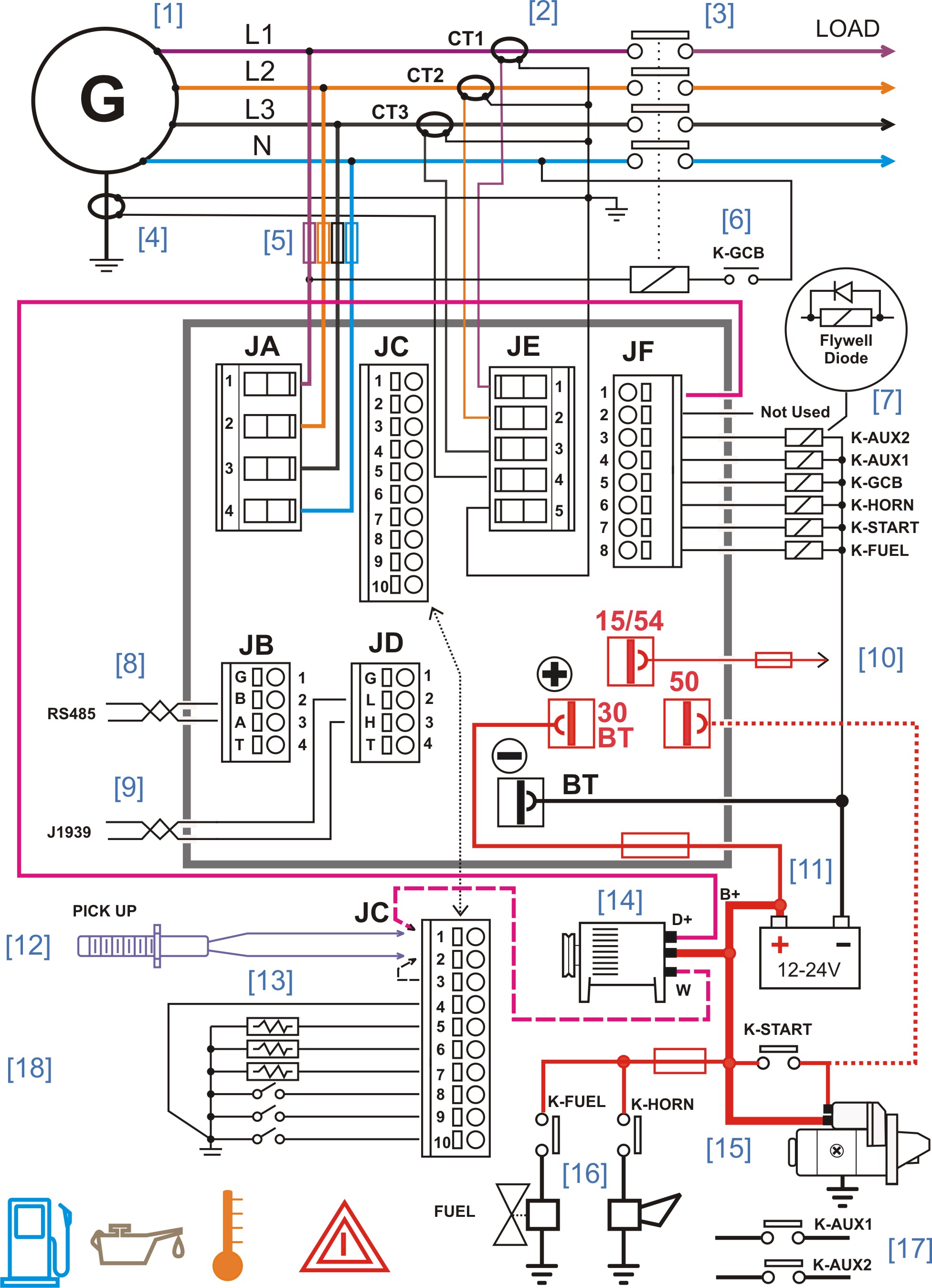
Auma actuator wiring diagram pdf. Appendix a standard wiring diagram legend page 50 original wiring diagram and legend are delivered together with the actuator. Indication lights of local controls 25 431. The wiring diagram shows the non rotating multi turn actuator in intermediate position. 1 technical data actuators multi turn actuators. Status indications according to auma classification 23 423. Please enter the address of our website in the address of web site to allow box.
If the pop up blocker is turned on in your browser you are not able to view the wiring diagram. Wiring diagram for standard version multi turn actuator closes valve clockwise. Legend for standard wiring diagram. Operation instructions manual sar 3 sar 100 sa 3 sa 100. 8 wiring diagrams 219 actuators 220 amexc actuator controls 225 acexc actuator controls 232. Selected wiring diagrams under documents attention.
Status indications according to namur recommendation 24 43. Other applications require explicit written confirmation by the manufacturerthe. Change colour 26 5. Feedback indications from actuator and valve 20 422. Auma norm actuator 1g 10 to 200 hz for actuators with amexc or acexc integral controls resistant to vibration during start up or for failures of the plant. Appendix a standard wiring diagram actuator controls auma matic am amexb amexc operation instructions profibus dp 15.
Auma actuator controls are exclusively designed for the operation of auma actuators. Wiring diagram number quotation number. Control wiring may result in damage to the motorized valve. Y001931002en proposed wiring diagram for sa with 3 phase ac motor asv1111111 kmstp110001 issue 108 we reserve the right to alter data according to improvements made. Proposed wiring diagram for external sensors 3 wire technology 59 83. Proposed wiring diagram for external sensors 4 wire technology 60 84.
The wiring diagram opens in a pop up window.
