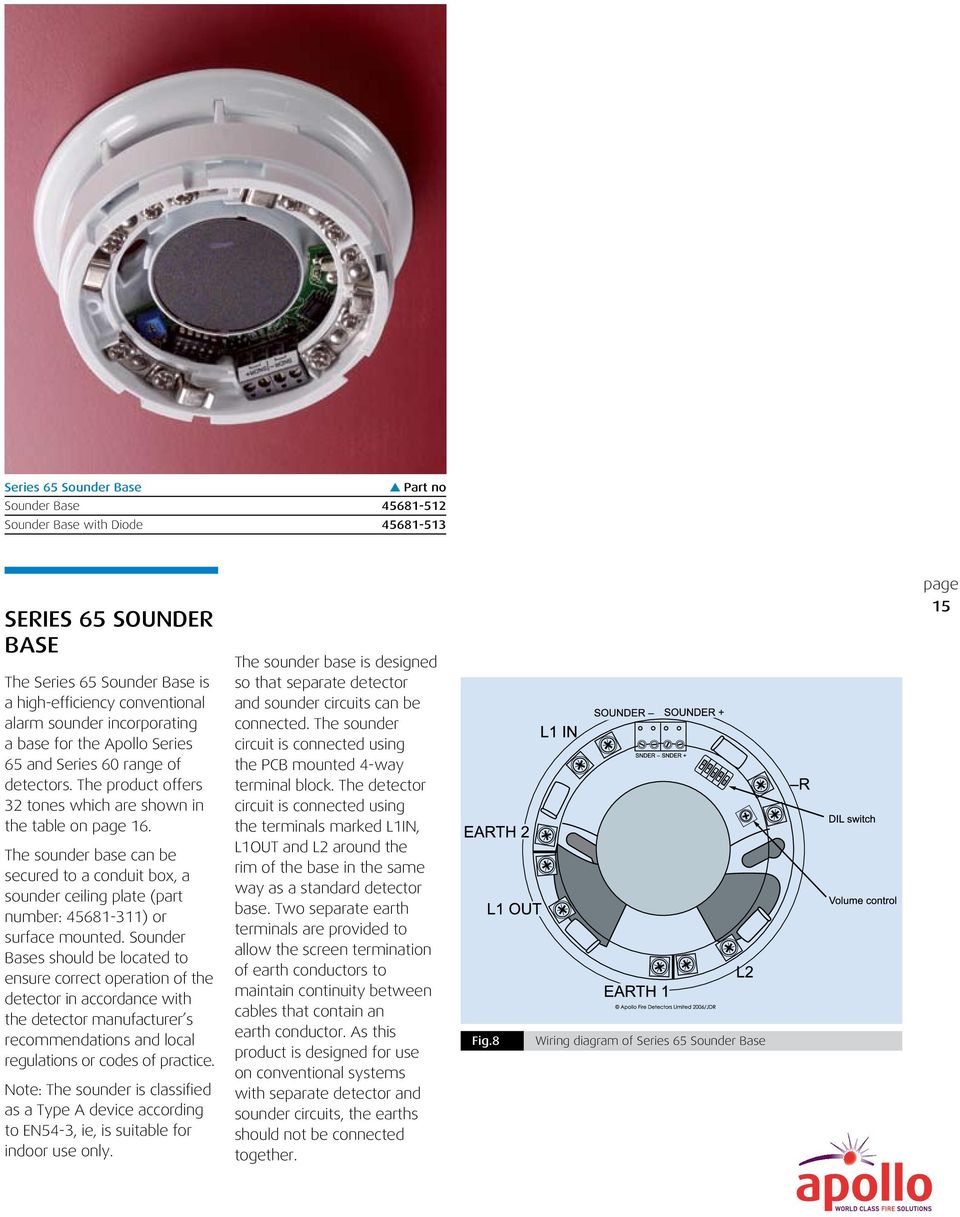
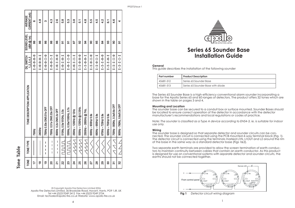
Series 65 smoke detector wiring diagram apollo series 65 smoke within apollo smoke detectors series 65 wiring diagram image size 583 x 337 px and to view image details please click the image. The base is fitted with a schottky diode on the l1 in and l1 out wiring terminals.

Apollo Series 65 Range Now Available Discount Fire Supplies
Apollo series 65 base wiring diagram. Apollo 65 wiring diagram addressable smoke detector wiring diagram use wiring diagram. The series 65 diode base is designed for use with conventional systems that have manual call points and detector bases on the same circuit. This base can only be used with compatible control equipment. Apollo smoke detectors series 65 wiring diagram wiring diagram is a simplified up to standard pictorial representation of an electrical circuit. Detectors can be locked into place by a grub screw using a 15mm hexagonal screwdriver. Apollo 65 wiring diagram with apollo 65 wiring diagram image size 510 x 510 px and to view image details please click the image.
The series 65 diode base is designed for use with conventional systems that have manual call points and detector bases on the same circuit. It shows the components of the circuit as simplified shapes and the skill and signal connections amid the devices. Here is a picture gallery about apollo smoke detectors series 65 wiring diagram complete with the description of the image please find the image you need. This base can only be used with compatible control equipment. Page 2 11ºc below rating 70ºc 60ºc fig 2 wiring diagram of series 65a zone with common remote indicator control panel refer to wwwapollo fi recouk for compatible panels the above instructions cover the following base model. All series 65 bases have a one way only fit.
Here is a picture gallery about apollo 65 wiring diagram complete with the description of the image please find the image you need. Apollo 65 wiring diagram wiring diagram is a simplified satisfactory pictorial representation of an electrical circuit. It shows the components of the circuit as simplified shapes and the power and signal links amid the devices. The series 65 sav wire base 45681 206 is designed to allow series 65 detectors to be used in sav wire detection and alarm systems and can only be used in conjunction with a sav wire compatible control panel. The series 65 standard relay base provides one set of volt free changeover form c contacts that change state when the detector signals an alarm. Apollo series 65 diode base 45681 201.
The base is fitted with a schottky diode on the l1 in and l1 out wiring terminals. The base incorporates a circuit which detects the removal of a detector head. Der relaissockel der serie 65 bietet einen potentialfreien wechselkontakt der seine schaltposition ändert wenn der brandmelder in den alarmzustand wechselt. 45681 200 4 mounting base 45681 220 6 mounting base 45681 232 low profi. The series 65 standard base has been designed to enable detectors to be fitted without the need of force particularly useful when fitting to suspended ceilings. If a detector is removed from the base the control panel will give a fault signal.


-500x500.jpg)


