Look carefully at the pic above. Diy tech repairs 62977 views.

Bms Module Setup Testing 24v 18650
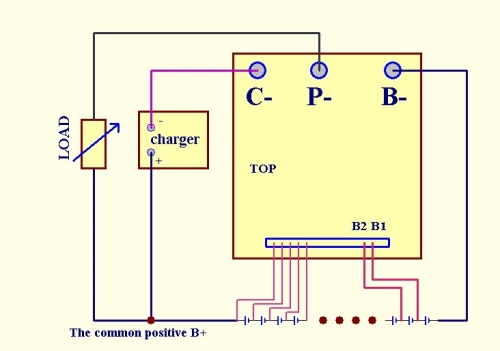
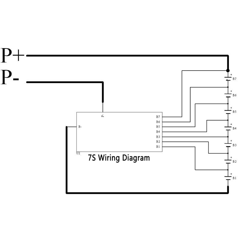
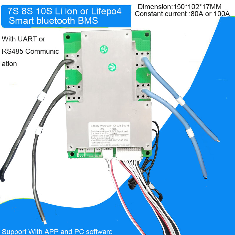
7s bms wiring diagram. Your final connections should look like this. These are the b p and c wires or pads for adding wires. If your bms comes with the thick wires already soldered to the bms board like the bmss sold in our shop then the hardest step is already done for you. 24v 7s bms for lithium ion cells. 24v 25a 35a 45a 60a 100a 200a. I usually start with the b wire.
Your bms will likely have 3 thick wires or 3 pads to solder on your own heavy gauge wires. Includes 7s balance wires. Notice how if a connection is made on the top side of the battery it is left open on the bottom and vice versa. Top five useful knots for camping survival hiking and more duration. Look at the wiring diagram at the top of step 6 again to see which connections you need to make. Smart bms review cheap choice for those with low budget duration.
All common bmss are wired in the same way. The white plug connects the dumb harness to the smart bms. A basic bms wiring scheme for a 7s pack. 24v 7s battery management system bms quantity. Please make sure you read the instructions in that article so. See my other video for sensor wiring.
Once you understand the pattern you can expand this to any size of pack. You can see that for the bms to access the positive and negative ends of the first cell and the connected first p group it uses the. This way we are always wiring the modules in series. The wiring diagram for this bms is shown below and you can read an article showing you how to install a bms on your vruzend kit here. I will be wiring a. Ill show how and where to connect the b c and p to the battery charger and power output.
Wiring diagram 24v 7s ev bms battery management system email a friend. Only 3 left in stock. Ev bms battery management system for 7 lithium li ncm battery packs in series 7s bms fundamentals explained instructions for paralleling strings of batteries.


