Refer only to the wiring diagrams illustrated in. An innovative partner webasto develops and engineers applications for both oe and aftermarket.
Webasto
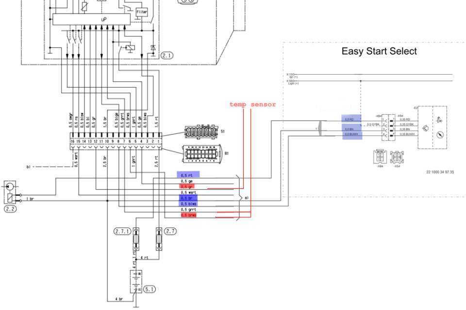
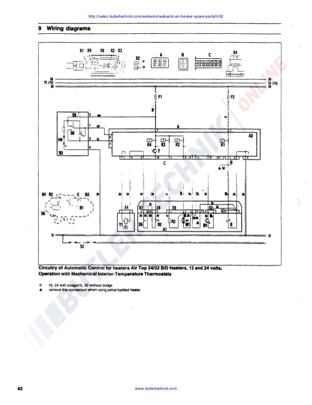
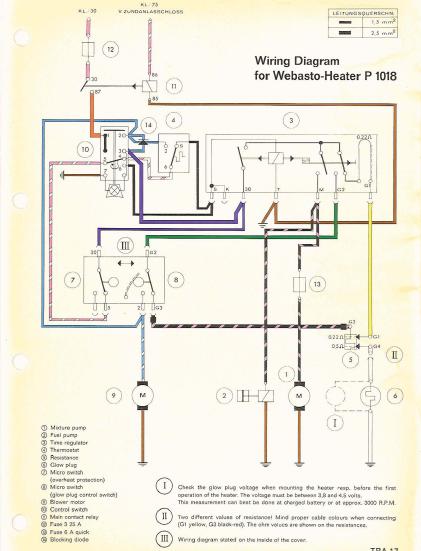
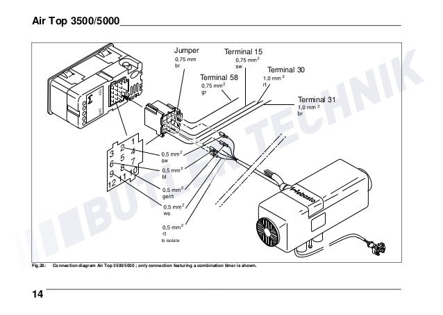
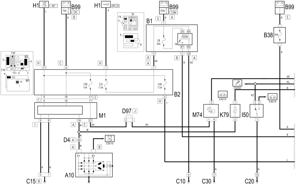
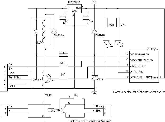
Webasto heater wiring diagram. Wiring diagram tsl 17 12 volt with optional digital timer. Webasto heater wiring diagram webasto airtop 2000 wiring diagram regarding webasto heater wiring diagram image size 1044 x 729 px and to view image details please click the image. The wiring diagrams in the tsl 17 manual are intended for the 12 volt tsl 17 heater only. Webasto thermo 50 electrical schematic with onoff switch 24 volt figure 3. Route and secure the wire harness from the webasto heater to constant power source and cut harness to length. The webasto only seems to have 5 wires from it a black and orangered in the three cables if in a small 4 pin square plug may be the timer connection perhaps you can get a rover electrical diagram showing the wires.
They are not cleared for heating a transportation compart ment for dangerous goods. The wiring diagrams illustrated in the tsl 17 installation manual part number 907512. Keeping the future in the rear view mirror webasto is at the forefront in developing technologically advanced solutions. Circuit breaker connected to a constant power source. Installation not complying with the installation instructions release webastoinformation about controllers used with webasto heaters may be viewed by selecting from the menu above. Connect the positive leads to a 30 amp.
Webasto heater workshop service manuals pdf free download wiring diagrams repair fault codes. Page 5 wiring diagram scholastic series heater. Wiring diagram 24 volt thermo 50 with. The air heaters air top 2000 and air top 2000 diagnosis are used to heat the cabin defrost the windscreens. Heater solutions as a market leader webasto manufactures custom heating solutions for a variety of scenarios. Here is a picture gallery about webasto heater wiring diagram complete with the description of the image please find the image you need.
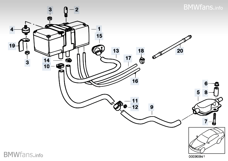
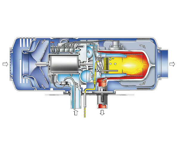
The heaters operate independent from the vehicle engine and are connected to the fuel tank and to the electrical system of the vehicle.
