2019 huntwise inc. It sounds like you have some wires crossed or possibly a defective unit.

Baby Mojo Parts
Mojo remote wiring diagram. Telecaster nashville wiring diagram. Burgaw nc 28425 phone. 12vmonster low voltage lights and gear 32191 views. This way you can manually control when the amplifier turns on and off by the flip of a switch. Another option for providing a proper remote turn on circuit is to wire constant power and ground to a switch and then wire the output of the switch to the amplifiers remote turn on. It doesnt have a real long range but for where i hunt the mojo is never really that far from me.
Search the keyword. Since my baby mojo has a 6v battery i thought id give it a try. Mojo self timer you should find tutorials and wiring diagrams. Stratocaster hss 5 way wiring diagram. Stratocaster standard five way wiring. Leave it to mojo the all new multiple decoy remote utilizes separate on and off buttons so that if any decoy should not turn on or off at the first try then one can send that signal again without it changing the opposite signal.
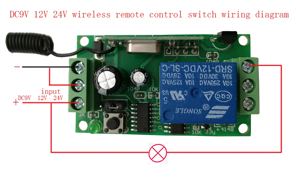
The problem with wiring the. I added a 13 wireless on off remote to my mojo teal. Comes wired to plug into any mojo decoy equipped wit the remote receptacle. The mojo remote only has three wires because one of the connections is internal on the circuit board. Remote will not operate under 3 volts. Telecaster three way wiring.
Telecaster four way wiring diagram. The mojo self timer can be used to program most small 612 v dc motors. 6 volt 6v wireless remote control for duck decoy mojo lucky 6v hunting decoy fowl hunter duration. In a motion goose decoy i have. Telecaster 3 way convertible wiring diagram. Wiring remote turn on to a switch.
Simply disconnect the positive wire red wire from your battery for 30 seconds. It came with two remotes and a reciever and was actually really simple to install into the mojos wiring harness. I use one to run a 12 v wiper mtr. This remote transmitter has a telescoping antenna and mojo embossed in the receiver. For identification purposes first make sure your battery is fully charged to approx. Site by holden t.
Pin 1 battery positive pin 2 battery negative pin 3 motor positive pin 4 motor negative via onoff switch.


