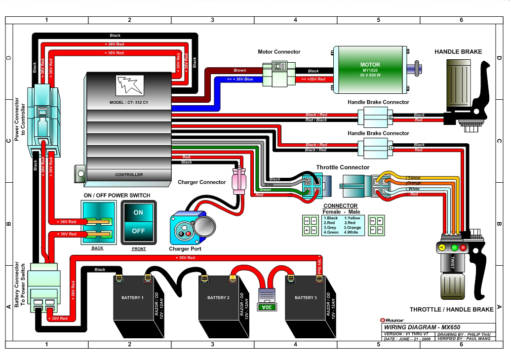
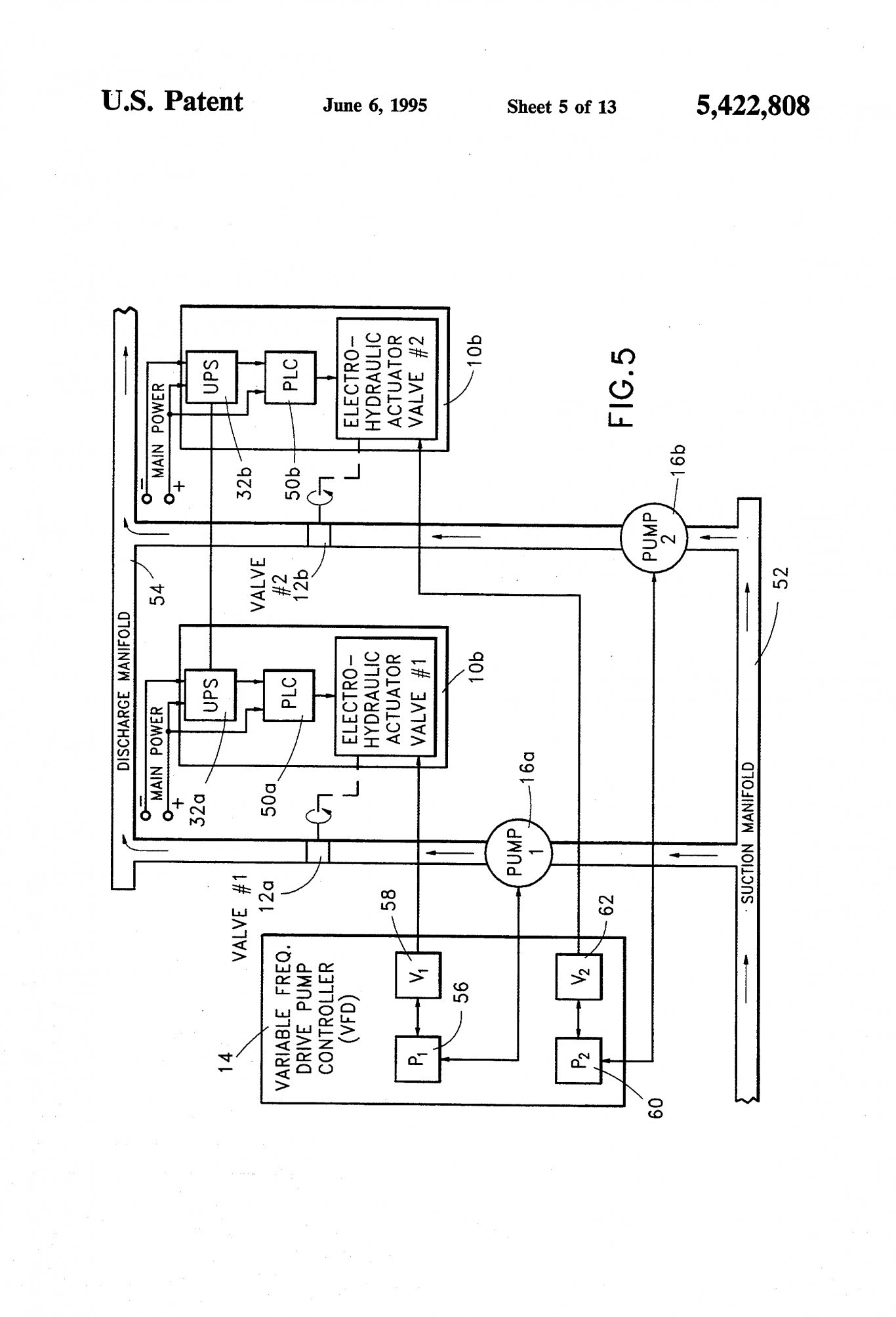
It reveals the parts of the circuit as simplified forms and the power and signal connections in between the tools. Manuals and user guides for flowserve limitorque mx 10.

Mercruiser Sterndrive Wiring Diagram Wiring Diagram
Limitorque mx 10 wiring diagram. Limitorque mx 10 wiring diagram nodasystech. Limitorque mx device net field unit. The wiring diagram for all standard mx actuators is shown on page 9. The following control features are included in the basic specification. Variety of limitorque l120 wiring diagram. Limitorque mx device net field unit.
Limitorque wiring diagram gallery. Wiring configurations for the mx and qx 28 121 mxqx terminal block 28 122 wiring diagram configurator 28 13. Figure 515 control module contactor assembly and wiring diagrams. Noah actuator wiring diagram dolgular of auma valve actuator wiring diagram image source. Limitorque electric actuator qx. Limitorque wiring diagrams are listed for most standard and optional electricalelectronic configurations of currently supported products.
Mxa wiring diagrams single phase. Limitorque wiring diagrams limitorque discover your wiring. A wiring diagram is a simplified standard photographic representation of an electrical circuit. Limitorque l120 actuators wiring diagrams. Limitorque limitorque accutronix mx protection control and monitoring features of mx electric actuators limitorque actuation systems fcd lmabr1300. Limitorque mx electronic actuator fcd lmenim2306 06 1013 2.
112 wiring 25 113 valve interface 25 114 design life and endurance 25 115 diagnostic features 26 116 factory test 26 117 conduit entries 26 118 european directives 26 12. 1 important notes 7 2 quick start 9. Limitorque l wiring diagram diagrams engine smb limit switch smc mx manual b actuators mx qx l drawings parts list programming setup mx suppliers quarter turn gearbox dimensions io image source. We have 1 flowserve limitorque mx 10 manual available for free pdf download. Control module contactor assembly and wiring diagrams 121 figure 515 continued 122 figure 516 encoder 130 figure 517 encoder drive cartridge 133 figure 518. 3 installation and operation 14.
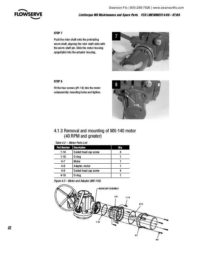
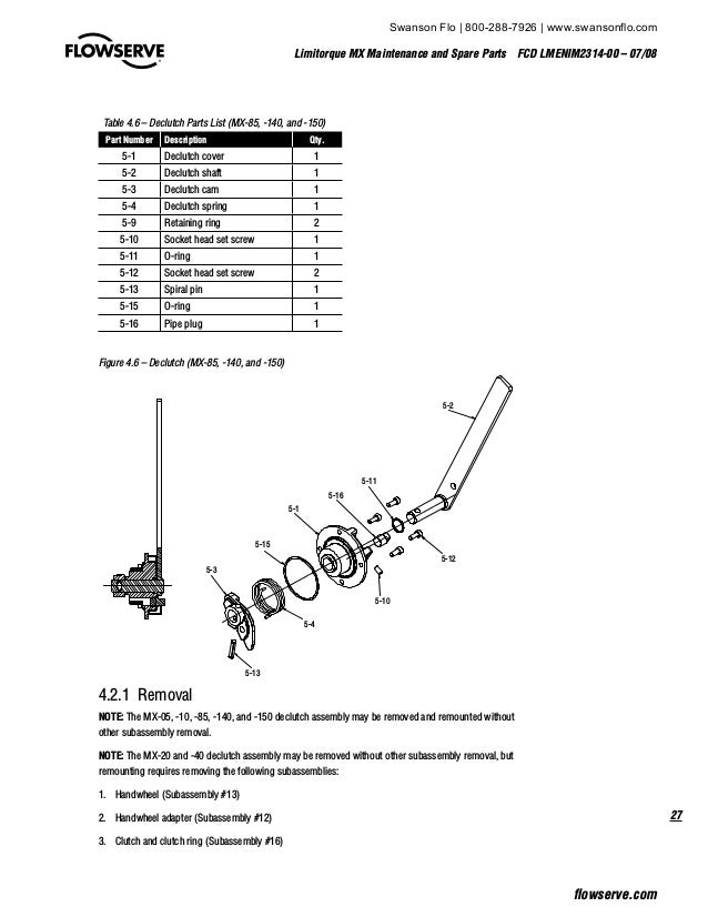
21 calibrate position limits 9 211 entering the setup mode 10 212 electrical operation feature 10 213 handwheel operation feature 11 22 ddcmodbus option 13 23 check the settings 13. Table 58 control module contactor assembly parts list. Mx and qx wiring diagrams 29 14. Units connect within most network configurations. Limitorque mx maintenance and spare parts fcd lmenim2314 00 0708 ii 45 side mounted handwheel with spur gear attachment mx 40 85 140 and 150 40.


