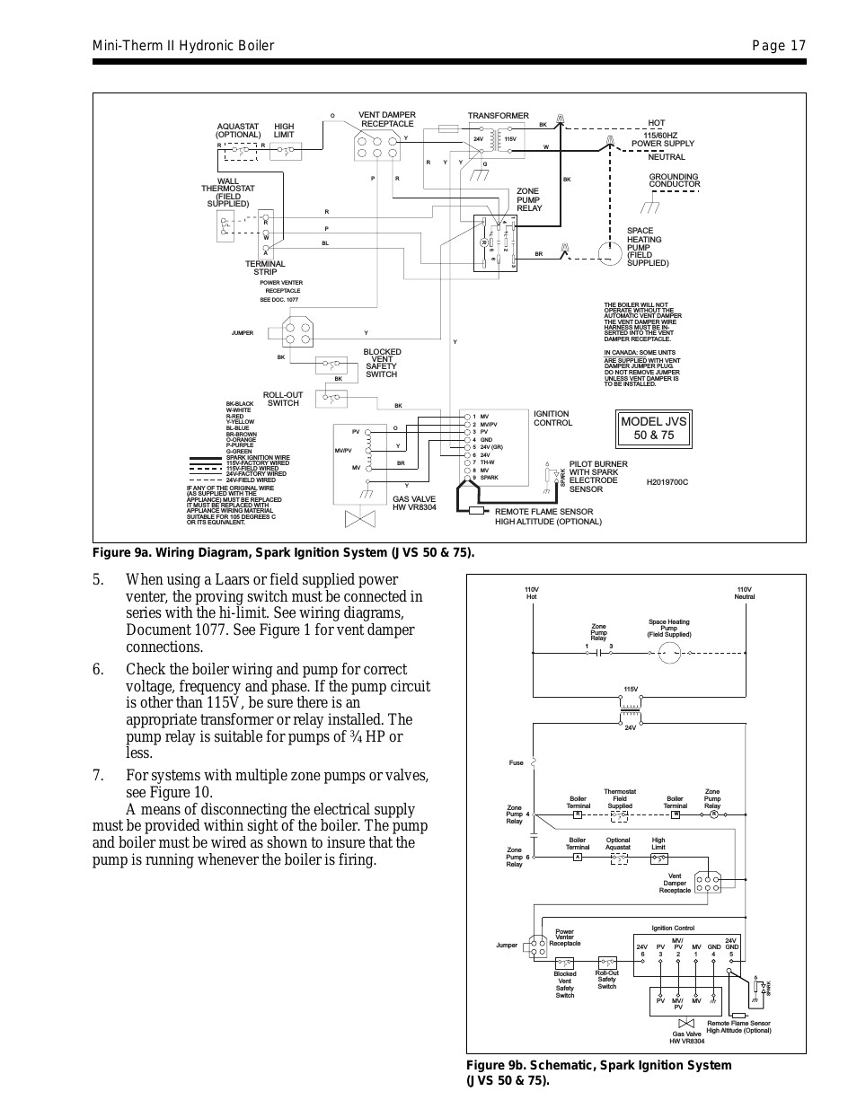
It shows the parts of the circuit as simplified shapes as well as the power as well as signal links between the tools. Variety of gvd 6 wiring diagram.

Gas Venting Dampers Gvd Models Field Controls
Gvd 5 wiring diagram. The field controls gvd series gas vent damper is packaged in a single carton containing an assembled gvd instruction manual and a plug. Some oem supplied units have the wiring harness attached. Keyed wiring harness connector plug installs only one way preventing incorrect wiring connection. Collection of onan generator wiring diagram. Variety of gvd 6 wiring diagram. Retrofit installations require a wire harness.
Gvd 4 thru 12 gas vent damper installation manual wiring diagram. It shows the parts of the circuit asa wiring harness is a 4 wire cable 8 feet meters long with d mating plug on one end and mating. Some oem supplied units have the wiring harness attached. Inspect for damage prior to the installation. A wiring diagram is a simplified traditional pictorial depiction of an electric circuit. Inspect for damage prior to the installation.
It reveals the components of the circuit as streamlined forms and the power and signal links in between the tools. Retrofit installations require a wire harne ss. Draw a horizontal line on diagram a or b that passes through the point located in step 5. The position of the point along this line relative to the left and right borders of the region it falls into indicates the relative position that the balance weight of the vrv should be adjusted to. A wiring diagram is a streamlined standard photographic representation of an electrical circuit. Installation manual and wiring diagram for gas vent damper models gvd 4 thru 12.
A typical standing pilot hookup with an added gas valve is shown in diagram a. 4 1316 how the gvd works. Gvd 6 wiring diagram a thy 1 1 cd8 pmel 1 t cells were at into c57b 6 mice one day prior to inoculation with 2 5 105 b16 tumor cells in matrigel. Order the universal wire harness 46390008. Gvd 6 wiring diagram building electrical wiring diagrams show the approximate areas and affiliations of receptacles lighting as well as irreversible electric services in a building. A wiring diagram is a streamlined standard photographic representation of an electrical circuit.
Adjoining wire paths might be revealed approximately where specific receptacles or fixtures need to get on a common circuit. The field controls gvd series gas vent damper is packaged in a single carton containing an assembled gvd instruction manual and a plug. If further information or additional wiring diagrams. Wiring diagram pics detail. The field vent damper is installed in the vent pipe after the draft hood or barometric. Order the universal wire harness 46390008.


