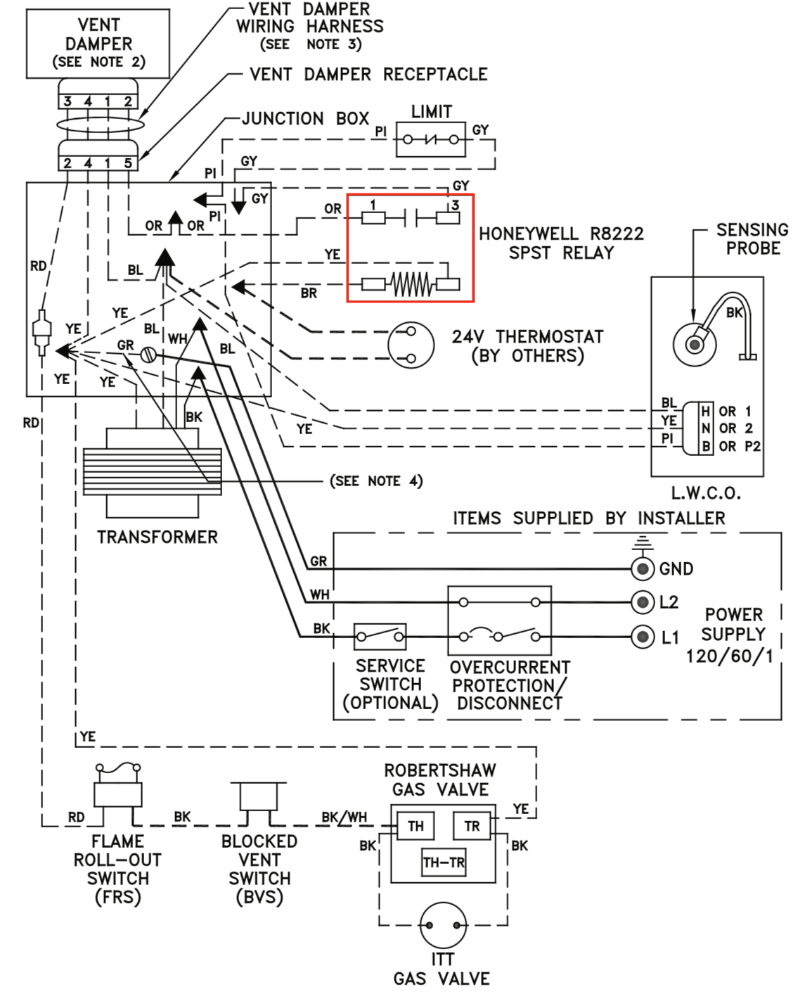
Use on a small motorcycle trailer snowmobile trailer or utility trailer. A wiring diagram is a simplified traditional pictorial depiction of an electric circuit.

Read Or Download 96 Ford Taurus Wiring Diagram Free Download
Gvd 4 wiring diagram. Order the universal wire harness 46390008. Can also be used as custom wiring on trailers with 3 lightwire systems. Collection of onan generator wiring diagram. The field controls gvd series gas vent damper is packaged in a single carton containing an assembled gvd instruction manual and a plug. Inspect for damage prior to the installation. 3ø wiring diagrams 1ø wiring diagrams diagram er9 m 3 1 5 9 3 7 11 low speed high speed u1 v1 w1 w2 u2 v2 tk tk thermal overloads two speed stardelta motor switch m 3 0 10v 20v 415v ac 4 20ma outp uts diagram ic2 m 1 240v ac 0 10v outp ut diagram ic3 m 1 0 10v 4 20ma 240v ac outp uts these diagrams are current at the time of publication.
Manuals and user guides for field controls gvd 4. We have 1 field controls gvd 4 manual available for free pdf download. The red and blue wire can be used for brake control or auxiliary. Trailer wiring diagrams trailer wiring connectors various connectors are available from four to seven pins that allow for the transfer of power for the lighting as well as auxiliary functions such as an electric trailer brake controller backup lights or a 12v power supply for a winch or interior trailer lights. The field controls gvd series gas vent damper is packaged in a single carton containing an assembled gvd instruction manual and a plug. Inspect for damage prior to the installation.
Order the universal wire harness 46390008. Some oem supplied units have the wiring harness attached. Field controls gvd 4 manual 24 pages gas vent damper. 4 1316 how the gvd works. Retrofit installations require a wire harness. Installation manual and wiring diagram for gas vent damper models gvd 4 thru 12.
Keyed wiring harness connector plug installs only one way preventing incorrect wiring connection. Gvd 4 thru 12 gas vent damper installation manual wiring diagram. It reveals the components of the circuit as streamlined forms and the power and signal links in between the tools. 34 inch by 1 inch 6 way rectangle connectors right turn signal green left turn signal yellow taillight brown ground white. Gvd 6 wiring diagram building electrical wiring diagrams show the approximate areas and affiliations of receptacles lighting as well as irreversible electric services in a building. Retrofit installations require a wire harne ss.
The field vent damper is installed in the vent pipe after the draft hood or barometric. Adjoining wire paths might be revealed approximately where specific receptacles or fixtures need to get on a common circuit. Some oem supplied units have the wiring harness attached.


