3ø wiring diagrams 1ø wiring diagrams diagram er9 m 3 1 5 9 3 7 11 low speed high speed u1 v1 w1 w2 u2 v2 tk tk thermal overloads two speed stardelta motor switch m 3 0 10v 20v 415v ac 4 20ma outp uts diagram ic2 m 1 240v ac 0 10v outp ut diagram ic3 m 1 0 10v 4 20ma 240v ac outp uts these diagrams are current at the time of publication. 2 to 1 and 3 3 slow.
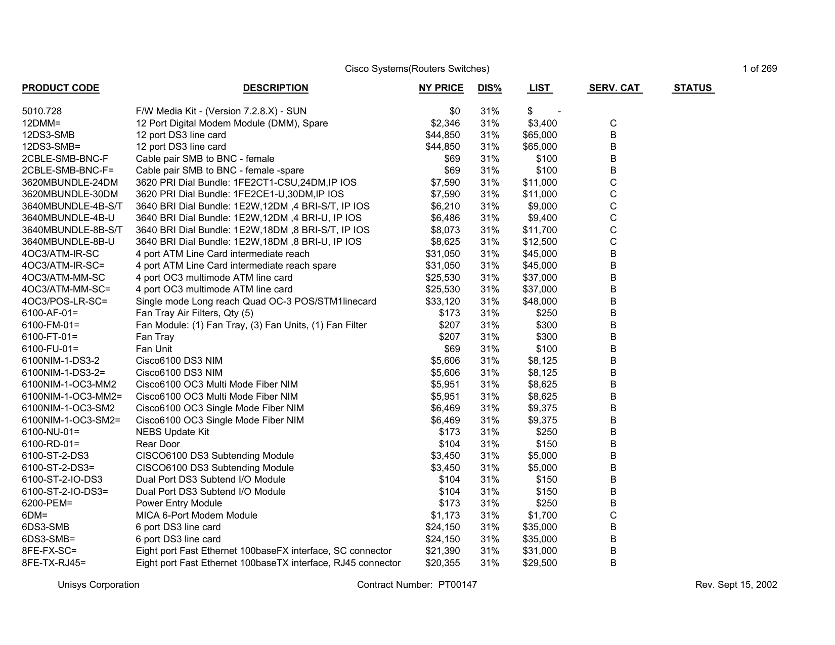
Cisco Systems Price List Office Of General Services Manualzz
Fan 2r cwe wiring diagram. Fcc id l3hjan95fan2r the wireless controller is not working any longer and i would like to find out what wires i. I have a hampton bay fan with a wireless controller model fan 2r cwe. Ceiling fan circuit type 2 canarm black speed switch with only three terminals connected two wire capacitor. The controller has a circuit board that controls if the fan or light is on and at what speed. This motor is a robbins myers psc motor incorrectly listed by skycraft as a capacitor start motor. There is a connecting wiring diagram pdf file below the deailsspecs.
Jun 27 im fixing a for a friend and need a wiring diagram or pictures or at least a description of the wiring. Speed switch connection table. T1t3t5 come from the motor with wire ends on them. Fcc id l3hjan95fan2r the wireless controller is not working any longer and i would like to find out what wires i need to connect together in order to just remove it and thus control the fan soley from a dual lightfan wall switch. No connection 1 fast. The black wire on the fan is the fan supply wire and thei have a hampton bay fan with a wireless controller model fan 2r cwe.
The standard hampton bay ceiling fan without a remote control has a straightforward wiring diagram. 2 to 1 2 med. I have a hampton bay fan with a wireless controller model fan 2r cwe. Fcc id l3hjan95fan2r the wireless controller is not working any longer and i would like to find out what wires i need to connect together in order to just remove it and thus control the fan solely from a dual lightfan wall switch.
