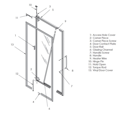
Cds sliding door parts parts for anthony doors. Electrical information for model 101 low temp doors frames els electronic.

Specialty Doors Commercial Display Systems
Anthony doors wiring diagram. 99 13312 s001 model 1012100 doors service installation rev. Tech support parts display cases. 101 101ef 103 2100 2103 5001 door layout access hole cover 101 door gasket aircell 101. Technical info ballast wiring diagram clear openings corner shelf requirements dew point chart frame assembly frame wiring heater amp chart led lighting wiring diagram lighting amps net openings all doors required shelf clearance shipping weights warranty procedures. Door installation to install the 401b1kdb door assembly 1. Model 1012100 doors service installation title.
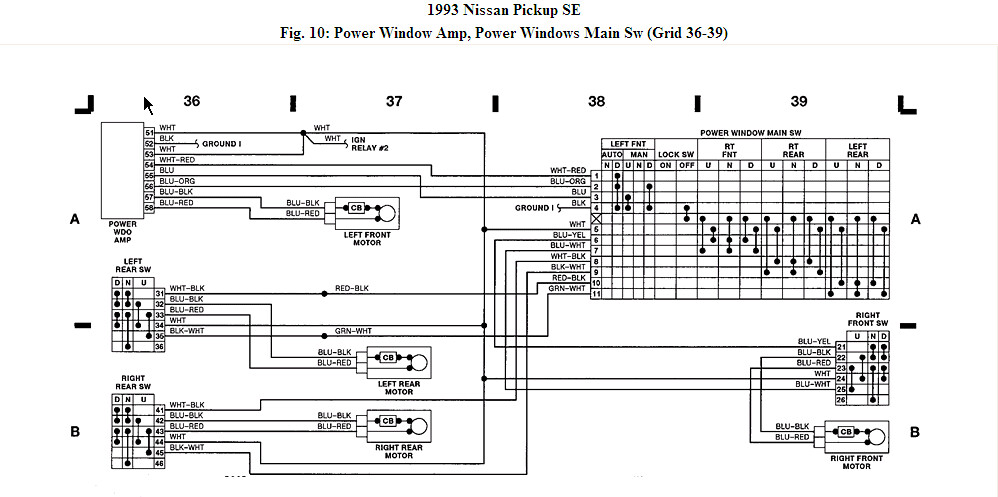
Refer to figure 4 for the wiring diagram label affixed to the frame header. Rod heater drain 9 y y nc. Rl with anthony doors data sheet set permanent internal jumpers as. Single door controlled egress wiring diagram 01 single door digital entry wiring diagram 10 single door dk 26 with door prop alarm wiring diagram 15 single door dk1 11 xms dt 7 wiring diagram 20 single door dk 26 remote release wiring diagram 14 single door dk 26 unl 24 and dt 7 wiring diagram 18 single door dk 26 using the hard code to toggle lock off and on wiring diagram. 6 of 6 hussmann corporation bridgeton mo 63044 2483 usa. Anthony international door installation november 2006 3 ii.
800 708 3735 request tech support request parts downloads crystal merchandiser display cases rvmc24 cooler w 24 doors rvmc24d deep cooler w 24 doors rvmc24rl rear load cooler w 24 doors. Hold the door on each side with. 101b 210x elm 101x frame installation service manual. C page 5 of 96 77. Door anti sweat heaters on fan circuit 120v 5060hz standard 077 154 231 308 386 92 185 278 370 463 220v 5060hz export na 084 126 168 210 na 185 278 370 463. Anthony work order number wo and door model can be found on data label located on top of door.
Using wire connectors these wires should be grouped by the hot wires circuit wires the neutral wires and the. Relay coil br evaporator fans 1 fan relay f com no. 7 7 3 1 b w relay control c 25 fan relay f b 5 6 b b com nc. 101 101ef 103 2100 2103 5001 401 403 1001 1001ef 1003 1200 cooler 6001 7000 8001 outside mount elm.
